Motor With Optical Control
Difficulty level: 3 (more difficult, requires the use of a soldering iron)
Kits covered: Kits #7,8

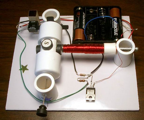
This motor uses an optointerrupter as a rotor position sensor. The
optointerrupter is an electronic device that consists of a light emitting diode
(LED) and a phototransistor with a slot between them. It is still quite simple
to build this motor from the kit.
When voltage is applied to the LED it emits light like an electric
bulb. However, the LED used in an optointerrupter emits an infrared light beam
which is invisible. Light emitting diodes are very reliable and consume a
relatively small current. Big current may destroy them, therefore a resistor
must be added to limit the current. Optointerrupters supplied with the kit (or
sold as a separate part) come with a 270 Ohm resistor which is suitable for
voltages in the range from 3 to 6V.
Phototransistors are specially
designed transistors with the base region exposed. These transistors are light
sensitive, especially when infrared source of light is used. They have only two
leads (collector and emitter). When there is no light the phototransistor is
closed and does not allow a collector-emitter current to go through. The
phototransistor opens only with the presence of sufficient light.
The picture below shows an
optointerrupter used in kits 7 and 8.

The motor with optical control uses a flat opaque disk with four blades attached to the rotor. When rotor spins the blades cross the slot and interfere with the beam from the LED to the phototransistor. The width of the blade greatly affects the efficiency of the motor as it determines how long the electromagnet stays on. The disk supplied with the kits is shown below. The blades are quite narrow so it consumes less current. With this width the motor may not start at 3V, but it works much longer in the range 4.5-6V.

If you decide to make a similar
disk yourself keep in mind that it should be dense as paper or even cardboard
might be semi-transparent for infrared light.
The output from the
phototransistor is very small and needs to be amplified. To make this motor as
simple as possible and minimize the number of parts, a Darlington transistor was
used. You may find information on this component at How
It Works: Reed Switch Motor With A Transistor.
The idea of using
optointerrupters in brushless motors is not new. However, optointerrupters are not widely
used because the motors based on them are complicated and require a lot of
parts. Dirt or a strong source of light pointed directly at the sensor may
affect the performance of these motors.
The motor with optical control is
very reliable (more reliable than a reed switch motor) and should work
indefinitely (actually, until mechanical parts wear down). This motor uses less
parts than any other existing motors with optical sensors.
This is how this motor works:
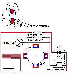
- In the starting position, the disk blade interferes with the channel between the LED and the phototransistor. The phototransistor stays closed and does not allow the current to go through it. However, the PNP power Darlington transistor in this case is open due to the way it is connected. This allows a collector-emitter current to flow through the electromagnet. The electromagnet then pushes magnet #3 away.
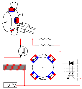
- When the magnets spin away, the disk moves out of the slot between the LED and phototransistor. The light signal to the phototransistor turns it on, and the phototransistor current turns the power transistor off. This disables the electromagnet.
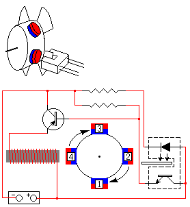
- The magnets continue to spin due to inertia until the next blade of the disk moves back into the slot. The phototransistor closes, and power transistor opens. Current through the electromagnet pushes magnet #4 away. This process continues until the power is disconnected.


This motor can be built from the Kit#7. Complete instructions are provided. However, if you decide to design this motor yourself, you may order only the parts you need (optointerrupter, PNP power Darlington transistor, magnet wire, magnets, heat sink).