Assembly Instructions: Conventional Motor
(Beakman's Motor Kit)
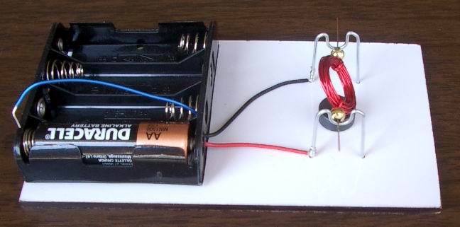
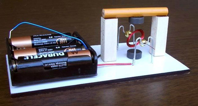
Difficulty level: 1 (the simplest, no special tools required)
![]() Printer-friendly assembly instructions in pdf format.
Printer-friendly assembly instructions in pdf format.
If you want to purchase this inexpensive and simple kit, click here.
Read all instructions carefully and check the Safety Rules before you start!
Introduction
The motor on this page is our version of well
known simple motor. You can find the motors like this in many books and on the
internet, for example Chris Palmer and Simon Quellen Field provided excellent
instructions and explanation how it works
at their sites (see Links section). The motor utilizing
similar design appeared on the Beakman's World TV show and now many people refer
to this motor as Beakman's motor. We call it a conventional motor because it is
not a brushless motor as opposed to all other motors on our site.
Though this kit looks like the simplest motor
it requires a lot of accuracy in balancing the coil and stripping off the
insulation. It is also not a very reliable motor. We found that it is
actually easier to assemble any of the reed switch motor kits shown at our site.
They are much more stable, reliable, may run non-stop for a long time, and are able
to do some work while practically nothing could be attached to
this motor. Therefore we recommend to use it as a learning tool or as a
comparison to brushless motors. This motor shares similar mechanical
design and looks nice placed side by side with one of our brushless motors.
This kit is very inexpensive, was tested extensively, and includes everything you
need to build the motor. Ordering it here also saves you one or more trips to
the stores.
Instructions
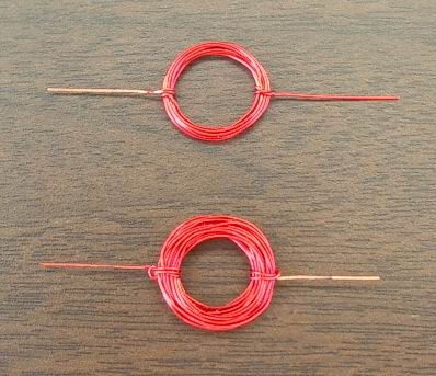
- Leave about 3" (7-8cm) and wind the wire 10-35 times around the AA battery. You do not have to be neat as some randomness does not affect the motor performance and may help the coil to hold its shape better. Leave 3" (7-8cm) at the other end of the coil.
- Carefully remove the battery and wrap the ends around the coil 2-3 times to hold the coil together with both ends extending perpendicular to the coil as shown below. The ends should be aligned in a straight line to form a good axle. This step requires a lot of accuracy because the balance of the coil is extremely important.
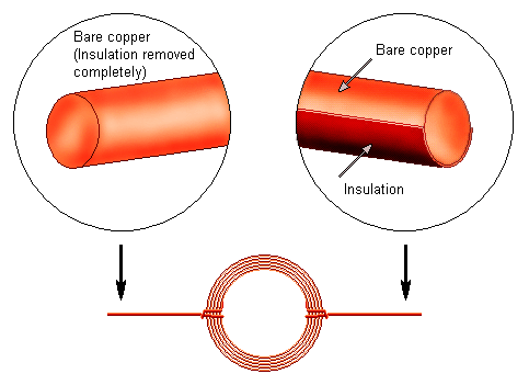
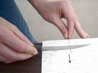
- Strip off the insulation completely at one end and only half of it at the other. This step is very important, try to be very accurate.
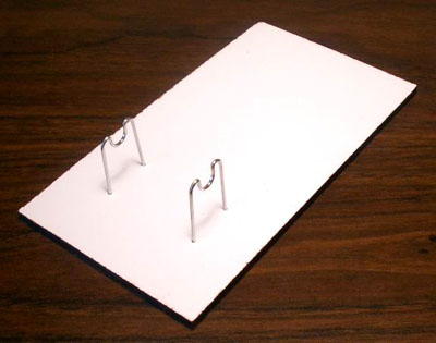
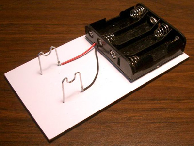
- Fully insert two metallic stands into predrilled holes in the board.
- Attach the battery holder to the board and connect its wires to the stands as shown below. You may need to cut the wires to the desired length. Do not forget to remove the plastic insulation at the ends of the wires.
- The battery holder and a jumper wire included in this kit allow you to experiment with 4 different voltages: 1.5, 3, 4.5, and 6 Volts. To understand how the jumper wire works let's take a look at the connections inside the battery holder:
- Glue the magnet to the board between the stands as shown below. Place two beads on the coil ends. These beads reduce the friction between the coil and the stands. Now place the coil on the stands and try to spin it slightly. Well balanced coil should spin freely. Ideally it should stop in random positions. Take time to balance it. You might need to move the ends up and down along the coil slightly to find the most balanced position. After you balance the coil you may add couple drops of glue where the ends meet the coil to prevent future sliding.
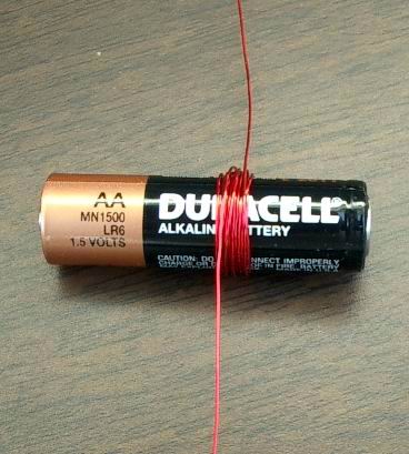
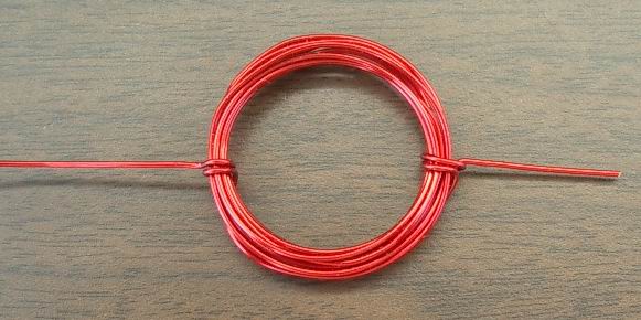
The kit contains enough wire to experiment with the coils of different size (10 and 30 windings shown).
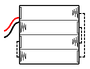
The following diagram shows how to get 1.5, 3, 4.5, and 6 Volts using 1, 2, 3, or 4 batteries and a jumper wire shown in blue color. Arrows show the current flow for 1.5, 3, and 4.5 Volts settings. Could you trace the current when all 4 batteries are inserted (there is no jumper wire in this case)?
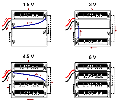
Insert bare ends of the jumper wire between the spring and plastic case to make a good contact and hold them in place.
Connect the battery and the jumper wire. Depending on the coil position the motor may start immediately or you might need to give it a slight push. The motor usually spins in one direction so you should try to spin it slightly in both directions. If the motor still does not work – click here for troubleshooting.

You can make this motor run faster by using two magnets. You will need a piece of sturdy material like heavy duty cardboard to make a crossbar. Piece of pencil is used in the motor below. Glue two stands to the board as shown in the picture. Before attaching the second magnet to the crossbar find the proper magnet orientation. Hold a second magnet over the top of the motor while it is running. If you move the magnet closer to the coil it may run faster or slower depending on which pole is facing the coil. Hint: South pole is marked on all supplied magnets and to make the motor faster North and South poles should face each other. After you find the proper magnet orientation glue the magnet to the crossbar and the crossbar to the stands.

You may have the magnets placed sideways as shown in the pictures below. However, when you strip half of the insulation as explained in step 3 you should lay the coil flat on the table or hold it so it is in a horizontal position.
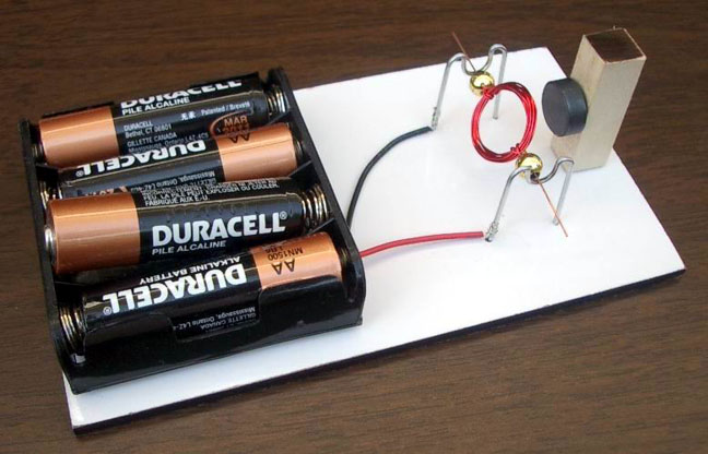
This is the motor with two magnets on the sides.
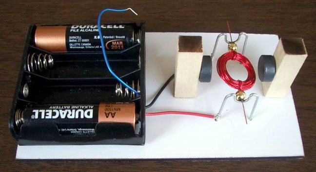
Start with one 1.5 Volts battery. If the motor does not work, add another battery to increase the voltage to 3V. If it still doesn't work, ensure that the rotor is balanced and can rotate freely and check the insulation. Properly removed insulation leaves shiny copper on one end. Half of the other end should also have shiny copper color while the other half should be the color of the original insulation as shown in step 3. Make sure the batteries are fresh and connected properly. If the motor still does not work – click here for troubleshooting.
CAUTION: Do not leave the motor connected to the batteries if the rotor is stalled. This motor consumes a lot of electricity and could drain the batteries quickly even if it does not spin.
If you want to compare this motor to the industrial conventional motor you may find some of them at our ordering page.
CONGRATULATIONS! You have finished
assembling this electric motor! If you want to experiment with this motor you
may find some useful ideas at Chris Palmer's site (see Links
section).
How it works
When un-insulated (bare copper) parts of the coil wire contact the metal stands the current from the battery flows through the coil making it an electromagnet with North and South poles. This electromagnet interacts with the permanent magnet (North and South poles attract each other while the same poles repel). Motor starts to spin until the contact is broken when an insulated part of the coil end comes into contact with the stand. However the coil continues to spin due to inertia and then the process continues. Technically speaking this motor is a single pole pulse motor.