Assembly Instructions: Experimentation Kit #1

Difficulty level: 1 (simple, but it is recommended using a multimeter to find a proper magnet orientation)
Experimentation Kit #1 is a variable speed control unit for the reed switch motors. It works with kits #1,2,3,4,5,8 and may work with any reed switch motor you built yourself. In some experiments it also provided good results with the motors on a Hall effect IC (kits #6, 8). This kit allows you to control and gradually change the speed of the motor from a complete stop to the maximum speed. It will even increase the normal speed of the motor 10-25%.
![]() Printer-friendly assembly instructions in pdf format.
Printer-friendly assembly instructions in pdf format.
If you want to purchase this inexpensive and simple kit, click here.
If you want to understand how it works, click here.
Read all instructions carefully and check the Safety Rules before you start!
Instructions
- Find the correct orientation of the
speed control magnet. CAUTION: If you glue the magnet incorrectly, the speed
control will still work; however, the consumed current will grow
significantly. This may quickly destroy the reed switch, drain the batteries,
and overheat the motor parts.
It is very easy to find the orientation of the magnet using a multimeter capable of measuring currents up to 2 A. A good digital multimeter is included in experimentation kit #3 and also available as a separate part.
Set the multimeter on the highest current measurement range (10A) and connect it to the motor as shown in the picture below. You will need to measure the consumed current of the motor.
Hold the magnet as shown in the picture and slowly move it from position A to position B. The motor should be working during this experiment. Watch how the consumed current changes. If the magnet is oriented properly, the current should decrease. If it grows, the magnet is oriented incorrectly. Turn it 180° so the other pole will be facing the reed switch. Remember this pole, it will face outwards when glued to the speed control stand. - Glue the magnet to the speed control stand. Once again, if the magnet is oriented properly, the consumed current should decrease when the magnet approaches the reed switch.
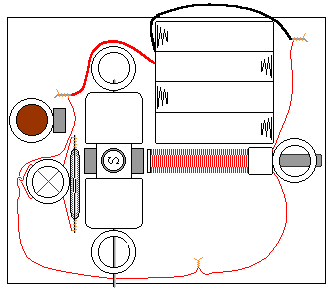
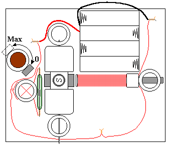
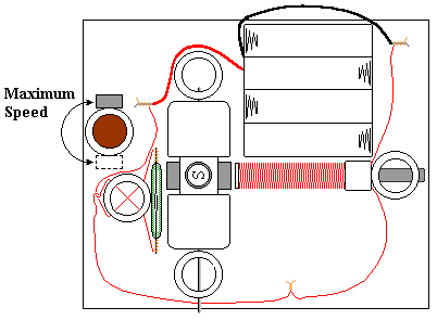
- Experiment with the speed control stand. Its approximate position is shown below. When you rotate this stand the speed of the motor should change according to the pictures.
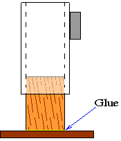
- After you find the best position for the unit, glue the inner stand to the board as shown below. The inner stand allows the rotation of the outer speed control stand.


If the outer stand rotates too easy and the vibration generated by the motor moves it, wrap the inner stand with a piece of scotch tape or thin piece of paper. If you are having difficulties inserting the inner stand you may need to sand it slightly with the sandpaper.