Reed Switch Motor
Difficulty level: 1 (the simplest, no special tools required)
Kits covered: Kits #1,2,3,4,8 and "Simple Motor You Can Build Yourself"
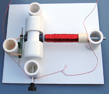
If you do not know much about electric motors, we recommend building this motor first. It is the
simplest motor with some real practical applications and it works very well. You may take a look at how easy it is to
assemble this motor from the kit you may order.
Most simple motors described either in books or on the Internet (see Links)
aren’t stable, reliable, or powerful
enough. Usually the brushes in these motors cause the problems. (In simple
conventional motors the coil spins in a magnetic field and moves between two
sliding contacts called brushes.) It is quite hard to make this part of the
motor accurate and reliable without having special tools, materials, and skills.
In 1997-2000 Stan designed and built for a school science fair project a reed switch
brushless motor, in which the
permanent magnets (this is the rotor) spin and the coil (this is the stator)
doesn’t move. The reed switch was used to sense the position of the rotor and to
change the magnetic field of the stator at appropriate times. This page explains the principles of Stan's original design, which provides excellent results despite its simplicity.
A reed switch consists of two magnetic contacts in a glass tube filled
with protective gas:

When a magnet comes close to a reed switch the two contacts become
magnetized and attracted to each other allowing an electrical current to pass
through. When the magnet is moved away from the reed switch the contacts
demagnetize, separate, and move to their original position.
Reed switches are very reliable and last as long as 3 billion
operations if used properly. They are designed for low currents. High voltages
applied to the contacts may cause a spark, which may weld the contacts together.
The best solution to this problem was recommended
by one of our visitors, Karl Mueller from the University of Michigan. He
suggested to use so called ZNR's. The ZNR is a little electronic device that
absorbs voltage and current spikes. It connects parallel to the reed switch and
practically eliminates the spark inside the reed switch glass tube.
This is how the motor works:
- When magnet #2 gets close to the reed switch the two contacts inside the glass tube get magnetized and touch each other. This causes the electromagnet to push magnet #1 away.
- When the magnets spin away, the reed switch demagnetizes and gets disconnected. This creates an open circuit disabling the electromagnet.
- The magnets continue to spin due to inertia until magnet #1 gets in working range of the reed switch. It becomes magnetized again and its contacts connect together making the electromagnet push magnet #2 away. This process continues until the power source is disconnected or depleted, or the reed switch is moved out of working range.
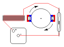
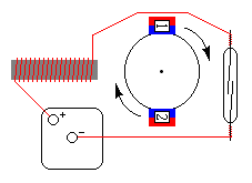
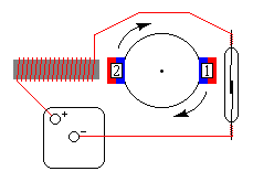
This motor can be built from Kits#1-4. Complete instructions are provided. However, if you decide to build this motor yourself, you may order only the parts you need (reed switch, magnet wire, magnets, ZNR). If you are a novice it is strongly recommended to use large and powerful reed switches in your designs as smaller reed switches are extremely fragile, may not last long enough, and it is very difficult to connect them without soldering their leads. We offer hard to find heavy duty reed switches that are appropriate for beginners.
The reed switch motor has a
unique advantage. It is very easy to control and change its speed with a few
additional parts. If you take an extra magnet and bring it closer to the reed
switch, its magnetic field will change the gap between the reed switch contacts.
A smaller gap allows the contacts to switch faster and therefore the speed of
the motor will increase, and vice versa.
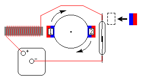
This allows you to control and change the speed of the motor from a complete stop to maximum speed, which may
be 10-25% greater than the normal speed of the motor.
You may move the magnet as shown above or rotate it near the reed switch. The following diagram shows how
different positions of an extra magnet affect the speed of the motor:
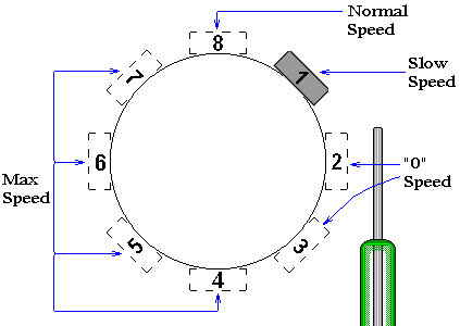
Orientation of the speed control magnet is very important. If it is oriented
improperly the reed switch contacts
may get connected permanently. It will create a short circuit, which may
overheat the wires and drain the battery quickly. It may also destroy the reed
switch.
The speed control can be added to any of the reed switch motors (kits #1-5 and #8) if you purchase
experimentation kit #1 or #3. Complete
assembly instructions describing an easy way to orient the speed control magnet are provided.